![[Emitter follower]](../gif/schem_follower.gif)
Emitter follower schematics
Author: Werner Ogiers
![[Emitter follower]](../gif/schem_follower.gif)
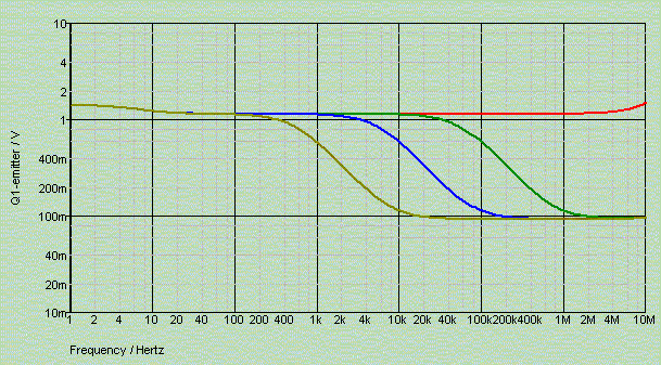
The output resistance of an emitter follower, assuming a sufficiently low impedance driving the base terminal, is approximately given by the formula R = 30 / Ic, with Ic the collector current in milli-Amperes. So at 1mA we expect to get 30 Ohms, and at 30 mA we get 1 Ohm. The bandwidth over which our regulator maintains this impedance corresponds to the band in which its current gain remains constant.

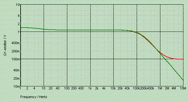
In our example R4 pulls some 28 mA from the transitor, yielding an emitter resistance at DC of just over 1 Ohm, as expected. This resistance is entirely maintained to over 1 MHz, as is demonstrated by the red trace in the above graph. With that high output resistance adding capacitors to it is a safe and predictable practice, the resultant curves being entirely non-resonant, dominated by the transistor in the lower regions, and by the capacitor's ESR in the higher frequencies. But note again that these simulations adopt ideal caps, ignoring ESL, and as such are not much better than worthless above 1MHz!


All fine and dandy, this resistive wide-band impedance, but with a magnitude above a whopping 1 Ohm it certainly is entirely useless for our purposes, not?
Well, not quite. There are a number of simple amplifier stages that have a high intrinsic PSRR, or that are otherwise not affected by high voltage rail impedance. These are circuits that typically do not impose a signal-related current on their supply lines, i.e. circuits that draw a (near-to) constant current only. Examples of these are balanced class A stages (not just any class A stage, as is commonly thought!), and folded cascode single-ended stages. For these the emitter follower voltage supply is a fine and economical solution that exactly provides what is needed most: low noise and wide bandwidth. That's why you find this primitive regulation scheme, or its JFET and MOSFET-based siblings, in some quite exalted commercial preamplifiers and phonostages! (Not referring to Naim this time.)
Now, if you want to try this regulator yourself, then please heed a word of caution: plugging in output capacitors C2 into a live circuit pulls an instantaneous current from the emitter large enough to kill the transistor in a flash. Be patient, and power-down the circuit before making any changes. And if you are in a hurry and insist on throwing caution to the wind, then at least insert a current limiting resistor in the transistor's collector lead. This may save you a lot of repair work.
[Rewind to Page 1] | [Rewind to Page 2]
© Copyright 2004 Werner Ogiers - www.tnt-audio.com