TNT Aircoil MKII Interconnects
A no compromise interconnect cable
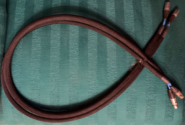
[ Home | Staff & Contacts | HiFi Playground | Listening tests | DIY & Tweakings | Music & Books ]

Product: TNT AirCoil mkII, no-compromise DIY interconnect cable
Manufacturer: not for sale, TNT-Audio DIY design
Manufacturing cost: between 100 and 250€
Reviewer: Piero Canova - TNT
Italy
Reviewed: December, 2021
I have to admit that making cables is, for me, a pleasant activity. Possibly it is because the electrical engineering competences demanded are not so great or perhaps I have worked in companies that had, among their customers, very large cable manufacturers, but I am always curious about any new possible solution and most of the time I always have some work in progress. November 2017 TNT presented an article by Roger McCuaig describing an interconnect cable made with solid conductors, PTFE insulated with the wires wrapped in a spiral around a PTFE center tube. You can call them parallel convergences because I had been working on a very similar solution so we wrote to each other comparing our ideas and results. The cable I am introducing to you today is the summary of all the tests I've made with the aim to achieve the best possible performance with a cost no object framework.
To build an excellent interconnect we need to start from some solid
foundations, so our cable must have a very low capacitance C, a low
inductance L, while we are ready to accept a slightly higher resitance R.
Any interconnect not having these characteristics should be considered, in
my view, with a lot of suspicion. L and C are strongly dependent on the
cable geometry we choose, so we will use the Aircoil geometry, but here we
reduce the wires to two and the crossings between wires will be at a pitch
of 20mm with a range between 15 and 25mm. This means that the two
conductors turn around the central tube one clockwise and the other
anticlockwise and they cross each other every 20mm on both sides of the
tube. This pitch is, for me, the best compromise between Common Mode
Rejection and low L and C. We will use a center tube of 10mm diameter and
as in the Aircoil project a drain wire inside the tube. In this way we
have correctly addressed the first order effects in a cable as categorized
by Thorsten Loesch here on TNT, but if we want to achieve the very best we
need to take proper account of the second and third order effects. Let's
consider the bandwidth necessary: normally we consider the audio spectrum
is between 20 Hz and 20,000 Hz, but several authors like Thorsten Loesch
or Allen Wright in his "The SuperCables Cookbook" (read our review) consider the necessary
bandwidth much more extended: Thorsten Loesch considers it between 4 Hz
and 100,000 Hz while Allen Wright says that an "extreme System" should
have a bandwidth of 0.2 Hz to 2,000,000 Hz. If we want to take in
consideration these recommendations then some second order effects aren't
secondary anymore and we need to consider them in the choice of materials.
Here we enter into a complex world populated by Maxwell's equations and
other complex mathematical formulas, but our humble purposes, we can
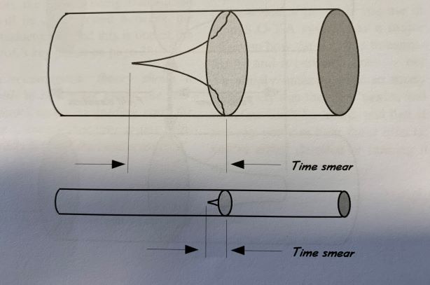
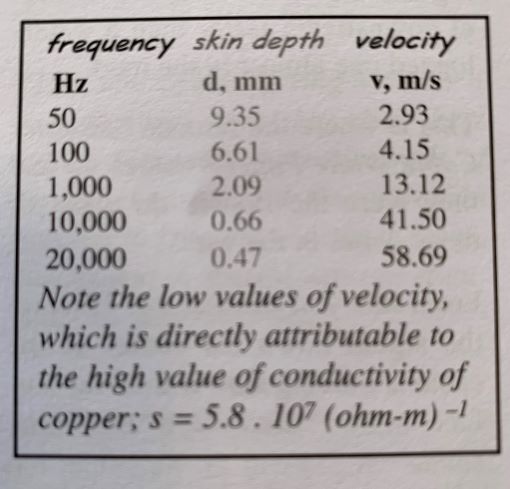
summarize them by saying that a solid conductor of the thinnest possible
diameter gives the minimum Skin Effect, Maxwell Effect and the time delay
or "time smear" that happens since different frequencies travel at
different depths of the conductor and also with a different speed. The
images here below explain better these concepts.
The ideal conductor should have the following characteristics: solid core, very thin, drawn with a very constant diameter, with outer surface mirror polished and without imperfections, of a very high purity and possibly monocrystalline. So far I haven't found anything having all there characteristics and the closest thing I have found is a Silver wire 0,2mm diameter, 5N or if you prefer 99,999% purity, with very polished surface. It is possible to find also 0,1mm wires, but they are almost invisible when you have to work with them and also very fragile so for practical limitations I am not using them. Using copper I have made cables with 0,14mm diameter, but copper is sturdier and the quality of material is lower. Unfortunately these wires aren't insulated so crossing them we will make a perfect short circuit, but we will see how to avoid the problem. As insulation we use PTFE that has the best dielectric properties among industrial products. The center tube should be also in PTFE, but pure PTFE has a snow white color and makes stiff wires that resist bending and when finally they give up, they crush like a metal tube. Flexible PTFE is modified for better handling, but it has a worse dielectric constant much like that of foamed PE: my choice was a solid PE tube wrapped with PTFE plumber's tape so the wires won't slip along it.
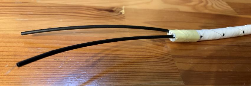
To make two interconnects one meter each long, cut two tubes 950mm long and wrap them with plumber's tape. With a ruler and a marker indicate the crossing points every 20mm: be careful not to smudge the marks off the PTFE during assembly. Start winding the first wire, following the marks; take good note of the direction of winding (clockwise or anticlockwise) and the distance of the first crossing point from the edge of the tube. Let the wire exit parallel to the tube and leave 10cm spare of wire each side. Use a piece of very thin heat- shrink tube to insulate the wire outside the tube and fix, with some tape, the insulated part to the center tube. So far you should have something resembling the picture here below.
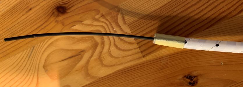
Notice how thin is the Silver wire: just three times larger than a human hair. Now we need to wind the second wire so we need to insulate the first. The solution I use is again plumber's tape. but this time we must be sure that there are no short circuits so we will use three layers of overlapped tape. Start from one end applying the tape; at the end of the tube cut and start it again, but turning in the opposite direction and again the same for the third layer. If you feel unsure or for added safety you can finally use a fourth layer of tape. This system offers a good level of safety, but you might be concerned that the final length of the two wires won't be the same since the second turns around a tube of larger diameter. The real difference is small, in order of 10mm, to be precise, but small imperfections could cancel the difference. Now you need to find the crossing points: having taken note of where is the first one you can easily mark the points again and lay the second wire. Remember to turn this wire in the opposite direction to the first one. Again leave 10cm free and insulate them with some heat-shrink, fix this to the main tube with some tape and use one last layer of tape to protect the second wire from rubbing and oxidation. With a multimeter check for any defect; it is relatively simple to correct any problem at this stage. Your cable should look like the image below.
Now insert the central wire inside the tube as explained in the Aircoil project: this wire will absorb the residual EMI if connected to the negative pin source side in the single ended configuration. It will also allow you to build a perfect balanced cable if connected on both ends of the cable. You can use a wire of any quality. I have chosen an AWG 24 copper wire that will help also in strengthening the wires running into the connectors. Please note that in single ended configuration these cables are directional since the connector with the central wire soldered as a drain must always be connected to the source equipment. When the cable is finished it is impossible to know which end is connected so make sure that you put some mark to the end to be connected to the source.
Screens: the same considerations expressed by Roger on Aircoils are valid. The more screens you put on the cable the more you increase C, you cut bandwidth on upper frequencies and the cable becomes "slow" so no screen at all is the best construction.
Finishing: put some heat-shrink on the three wires of the cable. An expanding sheath of the color you prefer will give a nice look to the cable and also will protect the wires inside. One last heat-shrink will fix the sheath and also the cables going into the connector.
Connectors:a cable of this quality deserves some serious connectors so we need to spend some money on them. I personally prefer Eichmann or KLE Silver Bullet. For balanced cables , I had in the past some discussions with Allen Wright and he agreed with me that Neutrik connectors with silver coated pins did sound much better than gold plated. Silver Bullets have the defect in that the cable lock system is not so solid and also limited in the diameter of the conductor accepted. If you plan like me to disassemble the cable because you want to recycle the connectors then just increase the diameter of the wires with some extra heat-shrink. If instead you want a very solid and reliable solution just pour inside the connector some epoxy resin and let it cure.
We have tested these cables in several systems and configurations. Tubes, solid state, single ended, balanced, lengths ranging from 70 cm to 2 meters: there was never any issue of compatibility. I cannot honestly say they were clearly better than every other cable they were compared with, but for sure, they weren't inferior to the other cables and, in many cases, we are talking about cables that are very, very expensive and exclusive. Several times the owners of the systems asked me to make, for them, some cables to replace those they had. Overall they are excellent, but in my view, they excel in four aspects: bass frequencies, soundstage, time coherence and speed. In bass frequencies the increase of clarity is evident; thin solid cores remove the bloat generated by thick fat cables, clearly improving the quality of sound. Thin wires minimize time smear allowing a much better coherence across the entire frequency spectrum. Low capacity design and no screening means a cable that is super fast in responding to transients. Honestly, I don't have a good explanation for the soundstage, but width and depth of the virtual stage are substantially increased where the system allows for it.
So far, this is the best geometry I have been able to design. The final cost is very much depending on the type of connector you want to use, but two balanced interconnects can be made for less than 100€ so we are still in the region of "reasonable". The skills to make them are average and they don't require too much time to make them. With a bit of attention to the details they can have also a nice look and a visible presence, satisfying the eye. I am strongly convinced that if you try them you will be very satisfied with them.
If you need help, do not miss our step by step tutorial with lots of pictures ad details.
DISCLAIMER. TNT-Audio is a 100% independent magazine that neither accepts advertising from companies nor requires readers to register or pay for subscriptions. After publication of reviews, the authors do not retain samples other than on long-term loan for further evaluation or comparison with later-received gear. Hence, all contents are written free of any “editorial” or “advertising” influence, and all reviews in this publication, positive or negative, reflect the independent opinions of their respective authors. TNT-Audio will publish all manufacturer responses, subject to the reviewer's right to reply in turn.
© Copyright 2021 Piero Canova - piero@tnt-audio.com - www.tnt-audio.com
[ Home | Staff & Contacts | HiFi Playground | Listening tests | DIY & Tweakings | Music & Books ]