Two-transistor Shunt Regulator

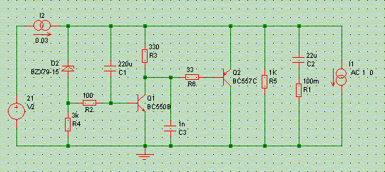
This is a slightly simpler version of the discrete transistor shunt you remember from the first article series. It has a somewhat lower open-loop gain (more on that later), and compensation capacitor C3 is added to ensure unconditional stability. Without any external aid it realises an impedance of 100 milli-Ohms, right up to 200kHz (way more without compensation).

Output impedance versus output capacitor C1: 0 (red), 2.2uF (green), 22uF (blue), 220uF (gold)
As shown above, even with small-value capacitors a flat and even impedance trace can be realised.

Influence of C2's ESR on impedance: 1mR (red), 10mR (green), 100mR (blue), 1R (gold)
Neither is this regulator sensitive to capacitor ESR, as it refrains from turning inductive below 100 kHz, so that crossing over with real-world capacitances is easy and free of resonances.

Electrical phase of output impedance, C2 = 22uF
This is an example of a flat and resistive impedance, with only a phase swing of 10 degrees in the audio band.
Two-transistor Shunt Regulator with High Gain
Our two-transistor shunt attained an output impedance of some 100 milli-Ohms. It did so over quite a wide frequency band, but limiting ourselves to below 10kHz or so, this is hardly better than what a TL431 manages, and five times worse than the LM317.
The reason is simple: simple as it is, this shunt regulator is a circuit with loop feedback around an error amplifier with limited open-loop gain. This amplifier is made up of transitor Q1 and its load R3, 330 Ohms in the above circuit.
The gain of this amplifier is easily calculated: R3 has 0.7V over it, and hence a current of 0.7/330 = 2 mA through it. This current also passes through Q1, and given the Re = 30/Ic rule, we find that Q1's emitter resistance Re is 15 Ohms. The total voltage gain then is R3/Re = 330/15 = 20.
The current running through the shunt transistor Q2 is 15 mA, hence its open-loop emitter resistance is 2 Ohms. With an open-loop gain of 20 and full feedback applied, the resultant regulator output impedance then is 2 Ohms / 20 = 100 mOhms.
Decreasing this impedance fundamentally calls for a higher open-loop gain around Q1. This is what the following two circuits attempt to achieve.

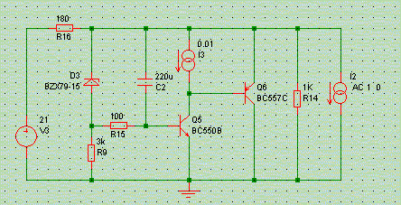
Feeding the top of gain-setting resistor R6 from a higher voltage than the regulated output voltage obviously allows a higher current through that resistor, and through the amplifying transistor. That transistor then gets a lower emitter resistance Re, and thus gain increases: 330/Re.
We get a higher top voltage by connecting R6 to an intermediate point in the series dropped resistor chain. In the above example R6 sees 18V on its top, or about 3V over itself. The current through R6, and the gain transistor, then is 10 mA, the transistor's Re is then 3 Ohms, and the resultant open-loop gain is then 330/3=110. With 10mA running through the shunt transistor this then yields an effective output impedance of 3 Ohms / 110 = 30 mOhms, see green trace below.

Output impedance of three versions of the two-transistor shunt: standard version (red), high-gain version with split voltage supply (green), high-gain version with current source load (blue)
All this gain for free? Of course not. You win some, you loose some. In this case the regulator's ripple rejection will have suffered. But that is another story.
(Caveat emptor: the above schematic is indicative only, and lacks all compensation to make it stable in the real world. If you try it, then keep this in mind!)

Even better can be had still, by replacing Q1's load resistor with an active load, i.e. a current source. The schematic contains an ideal current source, and as such reaches an output impedance well below 10 mOhms (blue trace). I leave it as an exercise to the reader to implement an active load there: the circuit will likely expand to at least four transistors, will unlikely to be unconditionally stable, and really will not deserve the name of 'simple voltage regulator' anymore.
[Rewind to Page 1] | [Rewind to Page 2] | [Rewind to Part 3]
© Copyright 2004 Werner Ogiers - www.tnt-audio.com