[ TNT | Who we are | Listening tests | HiFi Shows
| HiFi Topics | Tweakings
| Inter.Views | Termoionica
Applicata ]
Termoionica Applicata DIY projects
MW Pre 01 - Line Pre-amplifier with MM Phono Input
Uncommon Implementation of a Classical Design
A sophisticated grandson of the SIMPRE
Part 6
[Italian version]
The looks
From the point of view of look, well, black granite is a beautiful stone, but unhappily is typically used (in Italy at least) for tombstones and similar devices....
Definitely, an absolutely de-committing look had to be studied.
I decided immediately to use wood in order to reduce the dramatic (I should say funereal...) effect. Anyway, the risk of building a perfect funereal accessory remained really high :-)
As a first idea, I was thinking about a solid wooden front panel, 13 by 43 cm, hiding behind it the granite slab, with black sides; I made a coloured painting of the box, and, well, pretty funereal was it... hence I tough about using natural wood side panels, but the side view was not so pleasant, with the full height front panel, reducing to a thinner side panel, while upper and bottom slabs appeared. Moreover there was one more issue: the front panel was really enormous, completely plane and empty.
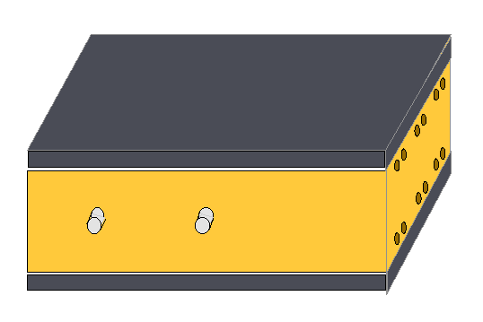
The final decision was to build just a square wooden belt, to be completely included between the two slabs, whose polished edge is visible on all sides of the box.
The front panel, at this point, is divided into three stripes: two 2cm granite upper and bottom stripes, and a wooden, (nearly) natural coloured, 9cm central stripes.
The look of the panel is rather unobtrusive, as a good deal of it is a dark grey, and hence not so visible, while the light wooden stripe is acceptable in height.
Cooling
In order to allow a little (and possibly not sufficient; but now it has been working without any trouble since July...) cooling of the rectifier tube, I had to make a few openings on the side of the box.
After a lot of studying, and in order to avoid major problems in wooden panels working, I decided to make this openings of the simplest form and size. At the top and at the bottom of the side panels I drilled a row of holes 1cm in diameter.
This holes are perfectly visible, so that their accuracy is definitely mandatory for a good aesthetic result.
This means that the greatest care must be taken in drilling them. But care is not enough: you must obtain perfectly smooth and edgy... hole edges. I applied an old technique that I knew could be applied to holes in the walls, but never thought possible to be applied to wood.
First thing is to mark, using a pencil, with the highest accuracy the centres of the holes to be drilled, typically with a cross several centimetres wide, directly on the side panel external surface (drilling must proceed from the external towards the internal surface).
With a sharp and possibly round tool you make by hand a little hole in the surface of the panel exactly in the centre of the hole; you can use even a sharp cutter, but in this case you must rotate it in order to get a perfectly round and central hole.
The real trick is now to cover the area to be drilled and a few centimetres around with masking tape (paper adhesive tape used typically for delimiting areas to be painted). The masking tape must be perfectly adherent to panel surface. You should better rewrite on the masking tape the crosses marking the centres of the holes.
Then you start drilling a hole with a small diameter (e.g. 3 mm) drilling point, using the little hole as guide and controlling the vertical asset of the drilling tool; then you enlarge the hole increasing step by step the point diameter (e.g. 6mm and 8mm), up to the final diameter (1cm). After any drilling operation you must check that paper is still perfectly adherent and that no wood powder has entered between it and the panel, pressing it again in order to be sure it perfectly sticks to the panel.
At the end, when you take the masking tape away, you find (hopefully... I was probably only very lucky....) a perfect hole. You could have to clean the hole edge at the internal panel surface, but I found really no other problem.
I decided to open the holes on both panels just for symmetry and aesthetic result; on the PSU side the holes remained open, and allow for PSU cooling, while on the other side the holes have been closed with a further little wooden panel applied with a few screws to the internal panel surface.
A step forward
One more hint. I decided to use black granite, for its isotropic behaviour and its homogeneous grain but also for its look, and was told that making holes through it is a very hard job.
Should you select another stone, marble for example, you could better ask for four holes to be drilled through the upper and bottom panels, near the corners, and then work a hole vertically through the wooden belt, in order to be able to insert long screws from the top to the bottom and use them to make all the structure solid and tight.
This could give very good results in terms of rigidity and stability of the structure; I am really sorry I did not ask for the holes to be worked out, as the structure is not as solid as I would like. Anyway, there is no real problem with sound even without screws.
As I had not had the holes drilled through the slabs, in order to make the structure a little more stable I used a lot of glue to connect two wooden blocks to the internal faces of the upper and lower slab, along the internal face of the side and back panels.
The side and back panels are then connected to the blocks with screws, partially hidden by the side ventilation holes. This can prevent accidental electrocution, but will not be able to prevent the structure to break down if unproperly handled.
Even if you take similar precautions, I want to repeat again what I said at the beginning: the structure is intrinsecally not coherent and can break down at any time, if you try to lift it sustaining it from the top or side panels (which is anyway difficult, given the not at all light weight).
I WAS NOT JOKING: IT CAN REALLY BE DANGEROUS. IF I HAD A CHILD IN MY HOME, I WOULD AT LEAST ENCLOSE THE WHOLE STRUCTURE INSIDE A NORMAL CABINET.

Functional blocks arrangement
I have just covered this point but I would like to repeat it here, in order to make everything as clear as possible; I think this is one of the most important (and less expensive...) design issues.
The overall functional block disposition has been accurately designed and tested. The major problem was circuits size: they are all rather complex and make large usage of good quality capacitors, which normally have a rather large size, especially paper and oil ones...
In order to avoid to have too a large cabinet I had to compress everything so that only few centimetres (or less...) separate one block from the other.
Another constraint in the structure layout was given by the presence of the volume and input selector shafts extensions that go through the whole structure, from the back panel to the front one, and cannot be obviously placed, for aesthetic reasons, too much off the centre horizontal line of the front panel...
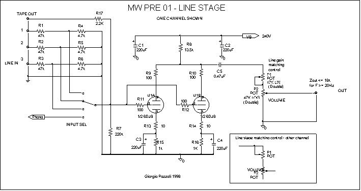
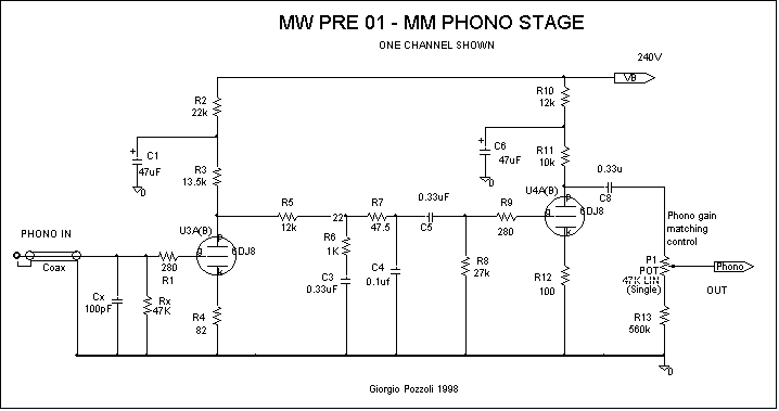
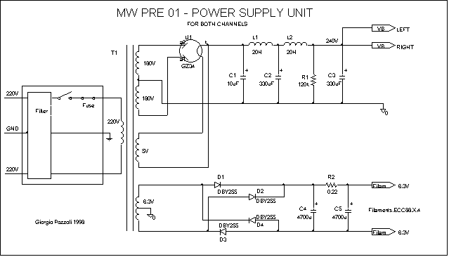
In the end the blocks have been placed in the best possible order: first power supply units, with rectifiers at the extreme side of the box, in order to reduce irradiated noise, and with the high voltage filtering stages orderly placed in sequence from the rectifier towards the centre of the box; then there is a wooden panel, with a aluminium foil over it, that is electrically connected to the side panels in order to achieve best irradiated noise separation between power supply and the audio circuit; then line stage and in the end the phono stage, just in front of the "input/output gear box" that is the box that contains all input pins, input selector, volume and balance potentiometers and output pins, that is placed at the back of the box and is completely closed and shielded to provide further insulation.
Tubes & Co.
All tubes are ECC88/E88CC/6922. ECC88 (Va=130V maximum) is perfectly adequate in all stages.
For phono stage low noise tubes should be selected.
The pre-amplifier sound depends heavily on the tube used. So it can be worth choosing lively, musical tubes, not too brilliant anyway if you use paper and oil capacitors everywhere.
I have not yet been able to make a full test with currently available tubes. What I can suggest you is to use Sovtek tubes in phono stage and something less noisy (for example low noise Golden Dragon) for phono stage. Anyway Sovtek tubes are a little more bright than I would like, and I have not yet been able to test Golden Dragon tubes.
I currently use Mullard gold pin in line stage and Philips ECG 6922 JAN in phono stage. Both of them are unhappily only available as NOS (or used…) tubes, but both are eminently musical, appreciably more musical than others ECC88 I have been able to listen to; Thorsten is using Philips Miniwatt NOS tubes and says they are really good.
Sovtek tubes are anyway really not so far, in the end: they just seem to be a little more brilliant, a little less full-bodied, and with all paper and oil I have in my prototype this could be a little too much. But really it is just a matter of taste.
Be careful: I have found problems with some Philips ECG 6922. As far as I was told, it seems that a few production lots of this tube have bad problems, they become noisy or start whistling after a while and the two halves are badly unmatched; anyway I have been also using a couple of these not so good tubes in line stage for a while, and they gave me not so many problems (and a really beautiful sound...).
Something about the other components.
All inputs and outputs are good quality, Teflon insulated, gold pins.
Input selector is a good, not horribly expensive, 2 ways 6 positions (only four are used) gold Palazzo axial selector.
Potentiometer, as said above, are all carbon low cost ones. Even though I was not able to find better ones, there are better quality carbon resistors available: it is probably worth looking for something better, at least for volume pot.
The others should be semi-fix potentiometers, hence durability is not so important. I repeat the hint above: I have completely covered with Teflon mummy tape my volume potentiometer, in an attempt to protect it from powder and similar amenities, and (apart the fact that now it seems a big cocoon...or else a mummy of a potentiometer…) up to now it has proved a good idea.
All resistors are Holco's, not too expensive, low noise and very precise.
All internal PSU wiring is either 1.2mm solid core silver plated copper wire (for all ground connections and buses) or multi-core, Teflon insulated, silver plated OFC copper (for all other connections). Filament wires are strictly twisted together.
All internal signal conductors are about 1mm solid core silver plated copper wire insulated by silk stirling tube; only exception, the phono conductor from input pin to phono stage is a multi-core, Teflon insulated, silver plated OFC copper very thin coaxial cable.


PSU Transformer specifications
|
Primary |
220-230V |
|
Secondary |
180+180V 100mA
6.3V 2A
5V 3A |
© Copyright 1998 Giorgio Pozzoli for TNT-Audio, http://www.tnt-audio.com
How to print this article
[ TNT | Who we are | Listening tests | HiFi Shows
| HiFi Topics | Tweakings
| Inter.Views | Termoionica
Applicata ]


